Study › Amateur Extra › E7G

E7G

PRACTICAL CIRCUITS

Operational amplifiers: characteristics and applications

Drill results are kept in this browser. Log in to keep them on your account and get a study plan.

E7G011 of 12

What is the typical output impedance of an op-amp?

Why An ideal operational amplifier has infinite input impedance, infinite open-loop gain, and zero output impedance. Real devices come close: input impedance is in the megohms or higher, and output impedance is typically a fraction of an ohm to a few ohms, especially once negative feedback is applied. A very low output impedance means the output voltage barely sags when the op-amp drives a load, so the stage acts like an ideal voltage source.
Watch out Very high describes the op-amp's input impedance, not its output. The specific values like 100 ohms or 10,000 ohms are too large for an op-amp output and just look plausible.
Op-amp ideal: input impedance infinite, output impedance zero, gain infinite. High in, low out.
HamSandwich explanation, first draft. The question and answers are the NCVEC text.
E7G022 of 12

What is the frequency response of the circuit in E7-3 if a capacitor is added across the feedback resistor?

Why In the inverting op-amp of figure E7-3 the gain is set by the ratio of the feedback impedance to the input resistor, gain = -Zf/R1. Putting a capacitor in parallel with the feedback resistor makes Zf drop as frequency rises, because the capacitor's reactance Xc = 1/(2*pi*f*C) shunts the resistor. So low frequencies see the full resistor and full gain, while high frequencies see a shrinking impedance and falling gain, which is low-pass behavior with a corner at f = 1/(2*pi*Rf*C).
Watch out High-pass is what you get by putting the capacitor in series with the input resistor instead, where the series reactance blocks the low frequencies from reaching the summing junction.
Cap across the feedback resistor shorts out the high-frequency gain: feedback C = low-pass; series input C = high-pass.
HamSandwich explanation, first draft. The question and answers are the NCVEC text.
E7G033 of 12

What is the typical input impedance of an op-amp?

Why An ideal operational amplifier draws essentially no current at its inverting and non-inverting inputs, which means its input impedance is effectively infinite. Real devices come close: bipolar-input op-amps are typically in the megohm range, and FET or CMOS input stages reach thousands of megohms or more. That very high input impedance is what lets an op-amp sample a signal without loading the source, so the gain is set almost entirely by the external feedback resistors. The companion ideal traits are very low (near zero) output impedance and very high open-loop gain.
Watch out The specific figures like 100 ohms or 10,000 ohms look like plausible circuit values, but those are more typical of an op-amp's output loading or of ordinary discrete transistor stages, not the input of an op-amp. Very low describes the output impedance, not the input.
Op-amp ideal: input impedance very HIGH, output impedance very LOW, gain very HIGH.
HamSandwich explanation, first draft. The question and answers are the NCVEC text.
E7G044 of 12

What is meant by the term "op-amp input offset voltage"?

Why A perfect op-amp would put out exactly zero volts when both inputs are at the same potential, but real devices have small mismatches in the input transistor pair. Input offset voltage is the small differential voltage you must apply between the inverting and non-inverting inputs to force the open-loop output back to zero. It is typically a few microvolts to a few millivolts, and it matters most in high-gain DC amplifiers where the offset gets multiplied by the closed-loop gain.
Watch out The choice about the potential between the input terminals in open loop describes the normal input difference, which for a stable circuit is essentially zero; offset voltage is specifically the correction voltage needed to null the output, not whatever happens to be present.
Offset = the tiny nudge at the inputs needed to null the output. Think "zeroing the scale" before weighing.
HamSandwich explanation, first draft. The question and answers are the NCVEC text.
E7G055 of 12

How can unwanted ringing and audio instability be prevented in an op-amp audio filter?

Why In an active (op-amp) filter, high Q means the feedback network is very lightly damped, so any transient rings for a long time before decaying, and high stage gain adds to the loop gain that keeps that ringing alive. Excess loop gain combined with phase shift in the RC network can turn the filter into an oscillator. The cure is to keep both the per-stage gain and the Q modest, cascading several low-Q, low-gain sections when a sharp response is needed.
Watch out The choices that raise one parameter while restricting the other miss the point: gain and Q both feed the same loop, so pushing either one up brings the stage closer to oscillation, and a very high Q alone will ring even at unity gain.
Both knobs down: high gain plus high Q equals ringing. Cascade several gentle stages instead of one sharp one.
HamSandwich explanation, first draft. The question and answers are the NCVEC text.
E7G066 of 12

What is the gain-bandwidth of an operational amplifier?

Why An op-amp's open-loop gain is huge at DC but rolls off at 20 dB per decade above its dominant pole, so the product of gain and bandwidth stays roughly constant. That constant is the gain-bandwidth product, and it is numerically the frequency where the open-loop gain has fallen to unity (0 dB). Knowing it lets you predict usable bandwidth: a stage set for a closed-loop gain of 10 built from a 1 MHz GBW device works to about 100 kHz.
Watch out The idea of a maximum filter frequency is tempting because GBW does limit filter designs, but the specification itself is a property of the amplifier alone, not of any particular filter circuit built with it.
GBW = the unity-gain frequency. Gain times bandwidth is constant, so gain 1 means bandwidth is the whole GBW number.
HamSandwich explanation, first draft. The question and answers are the NCVEC text.
E7G077 of 12

What voltage gain can be expected from the circuit in Figure E73 when R1 is 10 ohms and RF is 470 ohms?

Why Figure E7-3 is the standard inverting op-amp stage, where the closed-loop voltage gain magnitude is set entirely by the external resistors: gain = RF/R1. With RF = 470 ohms and R1 = 10 ohms, 470/10 = 47. The ideal op-amp assumption (infinite open-loop gain, no input current) forces the inverting input to a virtual ground, so the same current flows through R1 and RF, making the ratio the gain.
Watch out The choice of 0.21 is the reciprocal, R1/RF, which is what you get if you flip the ratio; 4700 is the product of the two resistors, not a ratio.
Feedback over input: RF/R1. Big feedback resistor means big gain.
HamSandwich explanation, first draft. The question and answers are the NCVEC text.
E7G088 of 12

How does the gain of an ideal operational amplifier vary with frequency?

Why An ideal op-amp is defined by a set of perfect properties: infinite open-loop gain, infinite input impedance, zero output impedance, and infinite bandwidth. Infinite bandwidth means the gain is flat at all frequencies, so it does not roll off at all. Real op-amps do roll off, typically at 6 dB per octave above a low corner frequency, characterized by a gain-bandwidth product, but that is a departure from the ideal model.
Watch out The choices describing a decrease with frequency describe a real device's open-loop response, where gain falls off above the corner frequency; the word 'ideal' in the question is the signal that no such limitation applies.
Ideal means infinite: infinite gain, infinite input Z, infinite bandwidth. Flat response, no rolloff.
HamSandwich explanation, first draft. The question and answers are the NCVEC text.
E7G099 of 12

What will be the output voltage of the circuit shown in Figure E7-3 if R1 is 1,000 ohms, RF is 10,000 ohms, and 0.23 volts DC is applied to the input?
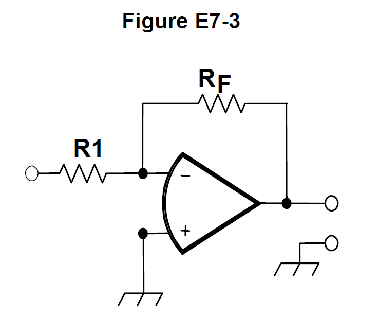
Figure E7-3 from the NCVEC question pool
Why Figure E7-3 is the standard inverting op-amp configuration: the signal enters through R1 to the inverting input and RF feeds back from the output to that same node. Its voltage gain is -RF/R1, so here -10,000/1,000 = -10. Multiplying by the 0.23 V input gives -2.3 V, the minus sign meaning the output is inverted relative to the input.
Watch out The choice showing +2.3 volts has the right magnitude but ignores the polarity inversion that comes from feeding the signal into the inverting (-) input; the 0.23 volt answers would require a gain of 1, which this resistor pair does not give.
Inverting amp: gain = -RF/R1. Ratio 10k/1k = 10, flip the sign, multiply the input.
HamSandwich explanation, first draft. The question and answers are the NCVEC text.
E7G1010 of 12

What absolute voltage gain can be expected from the circuit in Figure E7-3 when R1 is 1,800 ohms and RF is 68 kilohms?

Figure E7-3 from the NCVEC question pool
Why Figure E7-3 is the standard inverting op-amp stage, whose absolute (magnitude) voltage gain is simply RF divided by R1. Here 68,000 ohms divided by 1,800 ohms equals 37.8, which rounds to about 38. The minus sign that indicates phase inversion is dropped because the question asks for absolute gain.
Watch out The choice of 76 is what you get by doubling the answer, and 0.03 is R1/RF, the ratio inverted; remember the feedback resistor goes on top of the fraction.
Gain = RF/R1, feedback over input. Big feedback resistor means big gain.
HamSandwich explanation, first draft. The question and answers are the NCVEC text.
E7G1111 of 12

What absolute voltage gain can be expected from the circuit in Figure E7-3 when R1 is 3,300 ohms and RF is 47 kilohms?

Figure E7-3 from the NCVEC question pool
Why Figure E7-3 is a standard inverting op-amp stage, where the absolute (magnitude) voltage gain is simply the ratio of the feedback resistor to the input resistor, RF/R1. Here 47,000 divided by 3,300 gives about 14.2, so the gain rounds to 14. The minus sign that indicates the 180-degree phase inversion is dropped because the question asks for absolute gain.
Watch out The choice of 28 comes from doubling the ratio, and 0.07 is the reciprocal R1/RF, which would be an attenuator rather than an amplifier.
Inverting op-amp: gain = RF over R1, feedback on top. Divide, don't multiply.
HamSandwich explanation, first draft. The question and answers are the NCVEC text.
E7G1212 of 12

What is an operational amplifier?

Why An op-amp is an analog building block: it amplifies the difference between its two inputs (inverting and non-inverting) with very high open-loop gain, often 100,000 or more, and it is direct coupled so it works down to DC. Its input impedance is very high, so it draws almost no current from the source, and its output impedance is very low, so it can drive a load without the gain changing. Those ideal traits are what let external feedback components alone set the circuit's gain and response.
Watch out The choice calling it a digital audio amplifier gets one thing right, that external components set the characteristics, but an op-amp is an analog device, not digital, and it is not limited to audio.
Op-amp ideal: infinite gain, infinite input Z, zero output Z, differential and DC coupled.
HamSandwich explanation, first draft. The question and answers are the NCVEC text.
Icom IC-7300 HF/50MHz Base TransceiverSponsored · View on Amazon →Yaesu FT-991A HF/VHF/UHF All Mode TransceiverSponsored · View on Amazon →
← E7F All groups E7H →