E7B10
PRACTICAL CIRCUITS · Amplifiers: class of operation; vacuum tube and solid-state circuits; distortion and intermodulation; spurious and parasitic suppression; switching-type amplifiers
E7B10E7B →
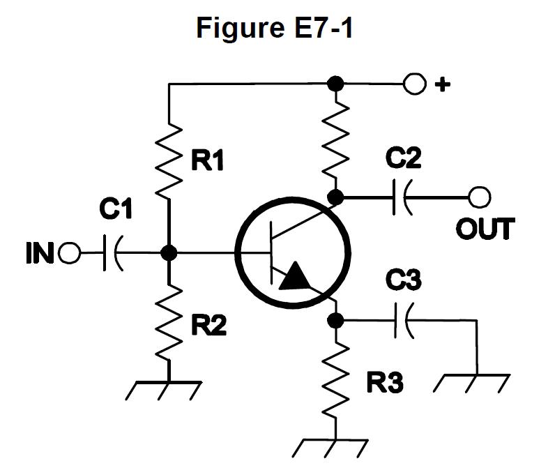
In Figure E7-1, what is the purpose of R1 and R2?
- ALoad resistors
- BVoltage divider bias
- CSelf bias
- DFeedback
Why In Figure E7-1 the two resistors run from the supply rail to ground with their junction tied to the transistor's base. That divider sets a fixed DC voltage at the base, which (minus the roughly 0.7 V base-emitter drop) sets the emitter voltage and therefore the quiescent collector current. This is the classic voltage divider bias network used to place a transistor stage at a stable operating point that does not drift much with temperature or beta.
Watch out Self bias describes a scheme where the device's own current through an emitter or cathode resistor develops the bias voltage, not a divider off the supply; load resistors would be in the collector or output path, developing the signal output voltage.
Two resistors in series across the supply, tap to the base: divider = bias. R1/R2 in E7-1 is always voltage divider bias.
HamSandwich explanation, first draft. The question and answers are the NCVEC text.
The rest of E7B
- E7B01 For what portion of the signal cycle does each active element in a push-pull, Class AB amplifier conduct?
- E7B02 What is a Class D amplifier?
- E7B03 What circuit is required at the output of an RF switching amplifier?
- E7B04 What is the operating point of a Class A common emitter amplifier?
- E7B05 What can be done to prevent unwanted oscillations in an RF power amplifier?
- E7B06 What is a characteristic of a grounded-grid amplifier?
- E7B07 Which of the following is the likely result of using a Class C amplifier to amplify a single-sideband phone s…
- E7B08 Why are switching amplifiers more efficient than linear amplifiers?
- E7B09 What is characteristic of an emitter follower (or common collector) amplifier?
- E7B10 In Figure E7-1, what is the purpose of R1 and R2?
- E7B11 In Figure E7-1, what is the purpose of R3?
- E7B12 What type of amplifier circuit is shown in Figure E7-1?