Study Amateur Extra E5C

E5C

ELECTRICAL PRINCIPLES

Coordinate systems and phasors in electronics: rectangular coordinates; polar coordinates; phasors; logarithmic axes

Log in to record drill results and track this group.

E5C01

Which of the following represents pure capacitive reactance of 100 ohms in rectangular notation?

  1. A 0 - j100
  2. B 0 + j100
  3. C 100 - j0
  4. D 100 + j0
E5C02

How are impedances described in polar coordinates?

  1. A By X and R values
  2. B By real and imaginary parts
  3. C By magnitude and phase angle
  4. D By Y and G values
E5C03

Which of the following represents a pure inductive reactance in polar coordinates?

  1. A A positive 45 degree phase angle
  2. B A negative 45 degree phase angle
  3. C A positive 90 degree phase angle
  4. D A negative 90 degree phase angle
E5C04

What type of Y-axis scale is most often used for graphs of circuit frequency response?

  1. A Linear
  2. B Scatter
  3. C Random
  4. D Logarithmic
E5C05

What kind of diagram is used to show the phase relationship between impedances at a given frequency?

  1. A Venn diagram
  2. B Near field diagram
  3. C Phasor diagram
  4. D Far field diagram
E5C06

What does the impedance 50 - j25 ohms represent?

  1. A 50 ohms resistance in series with 25 ohms inductive reactance
  2. B 50 ohms resistance in series with 25 ohms capacitive reactance
  3. C 25 ohms resistance in series with 50 ohms inductive reactance
  4. D 25 ohms resistance in series with 50 ohms capacitive reactance
E5C07

Where is the impedance of a pure resistance plotted on rectangular coordinates?

  1. A On the vertical axis
  2. B On a line through the origin, slanted at 45 degrees
  3. C On a horizontal line, offset vertically above the horizontal axis
  4. D On the horizontal axis
E5C08

What coordinate system is often used to display the phase angle of a circuit containing resistance, inductive, and/or capacitive reactance?

  1. A Maidenhead grid
  2. B Faraday grid
  3. C Elliptical coordinates
  4. D Polar coordinates
E5C09

When using rectangular coordinates to graph the impedance of a circuit, what do the axes represent?

  1. A The X axis represents the resistive component, and the Y axis represents the reactive component
  2. B The X axis represents the reactive component, and the Y axis represents the resistive component
  3. C The X axis represents the phase angle, and the Y axis represents the magnitude
  4. D The X axis represents the magnitude, and the Y axis represents the phase angle
E5C10

Which point on Figure E5-1 best represents the impedance of a series circuit consisting of a 400-ohm resistor and a 38-picofarad capacitor at 14 MHz?
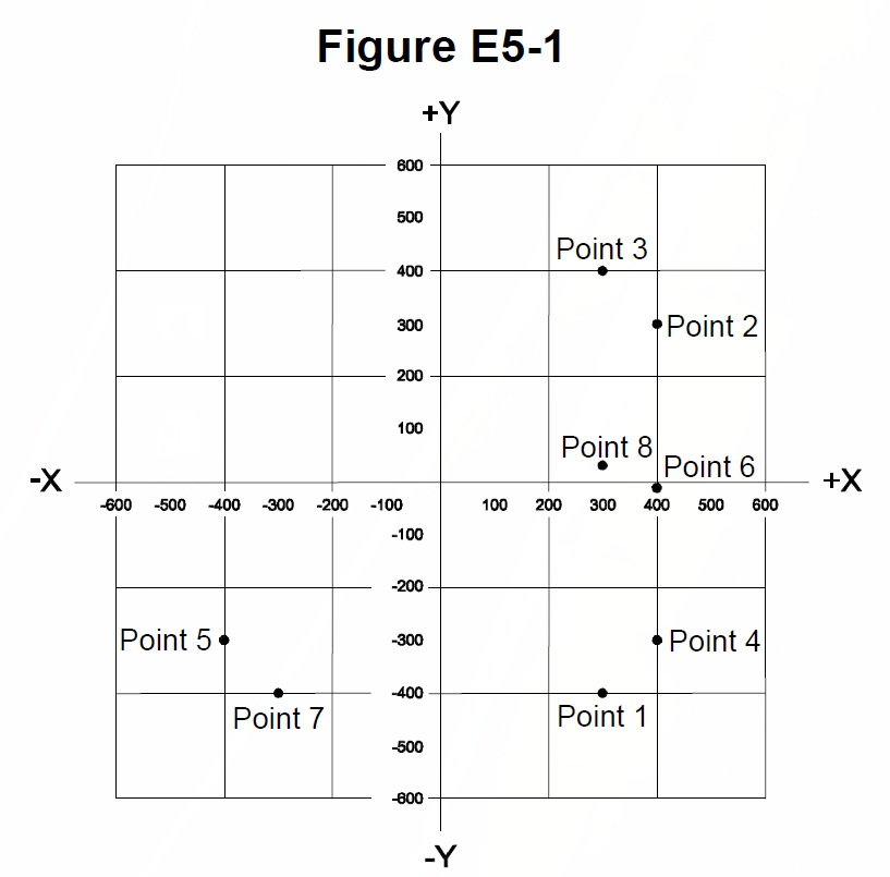
Figure E5-1 from the NCVEC question pool
  1. A Point 2
  2. B Point 4
  3. C Point 5
  4. D Point 6
E5C11

Which point in Figure E5-1 best represents the impedance of a series circuit consisting of a 300-ohm resistor and an 18-microhenry inductor at 3.505 MHz?

Figure E5-1 from the NCVEC question pool
  1. A Point 1
  2. B Point 3
  3. C Point 7
  4. D Point 8
E5C12

Which point on Figure E5-1 best represents the impedance of a series circuit consisting of a 300-ohm resistor and a 19-picofarad capacitor at 21.200 MHz?

Figure E5-1 from the NCVEC question pool
  1. A Point 1
  2. B Point 3
  3. C Point 7
  4. D Point 8
Icom IC-7300 HF/50MHz Base TransceiverSponsored · View on Amazon →Powerwerx SS-30DV 30A DC Power SupplySponsored · View on Amazon →
← E5B All groups E5D →