E5C11
ELECTRICAL PRINCIPLES · Coordinate systems and phasors in electronics: rectangular coordinates; polar coordinates; phasors; logarithmic axes
E5C11E5C →
Which point in Figure E5-1 best represents the impedance of a series circuit consisting of a 300-ohm resistor and an 18-microhenry inductor at 3.505 MHz?
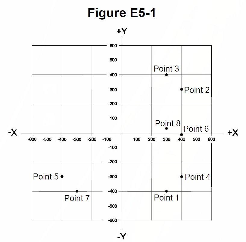
- APoint 1
- BPoint 3
- CPoint 7
- DPoint 8
Why Compute the inductive reactance first: XL = 2*pi*f*L = 2*pi*(3.505e6)(18e-6), which comes to about 396 ohms, essentially 400 ohms. In series the resistance and reactance add as a complex number, so Z = 300 + j396, roughly 300 + j400 ohms. On the graph that is a point 300 units to the right on the resistance axis and about 400 units up on the positive (inductive) reactance axis, which is Point 3.
Watch out The mirror-image point below the axis represents 300 - j400, a capacitive reactance, and points with the 400 and 300 swapped correspond to a different resistor and reactance pair, so check which axis carries which number.
XL = 2*pi*f*L; inductive means plot ABOVE the axis, capacitive below.
HamSandwich explanation, first draft. The question and answers are the NCVEC text.
The rest of E5C
- E5C01 Which of the following represents pure capacitive reactance of 100 ohms in rectangular notation?
- E5C02 How are impedances described in polar coordinates?
- E5C03 Which of the following represents a pure inductive reactance in polar coordinates?
- E5C04 What type of Y-axis scale is most often used for graphs of circuit frequency response?
- E5C05 What kind of diagram is used to show the phase relationship between impedances at a given frequency?
- E5C06 What does the impedance 50 - j25 ohms represent?
- E5C07 Where is the impedance of a pure resistance plotted on rectangular coordinates?
- E5C08 What coordinate system is often used to display the phase angle of a circuit containing resistance, inductive…
- E5C09 When using rectangular coordinates to graph the impedance of a circuit, what do the axes represent?
- E5C10 Which point on Figure E5-1 best represents the impedance of a series circuit consisting of a 400-ohm resistor…
- E5C11 Which point in Figure E5-1 best represents the impedance of a series circuit consisting of a 300-ohm resistor…
- E5C12 Which point on Figure E5-1 best represents the impedance of a series circuit consisting of a 300-ohm resistor…