T6C
ELECTRONIC AND ELECTRICAL COMPONENTS
Circuit diagrams: use of schematics, basic structure; Schematic symbols of basic components
Drill results are kept in this browser. Log in to keep them on your account and get a study plan.
What is an electrical diagram using standard component symbols called?
Why A schematic is the standard drawing that represents a circuit using agreed-upon symbols for resistors, capacitors, transistors and so on, plus lines showing the electrical connections between them. It shows how the circuit works electrically, not how the parts are physically arranged on a board or in a chassis. Because the symbols are standardized, any ham anywhere can read the same diagram.
Watch out A flow chart shows steps in a process or program, not electrical connections, and a connection or wiring chart deals with physical cabling rather than standard component symbols.
Schematic = scheme of the circuit in symbols; flow charts are for processes, not parts.
HamSandwich explanation, first draft. The question and answers are the NCVEC text.
What is component 1 in figure T-1?
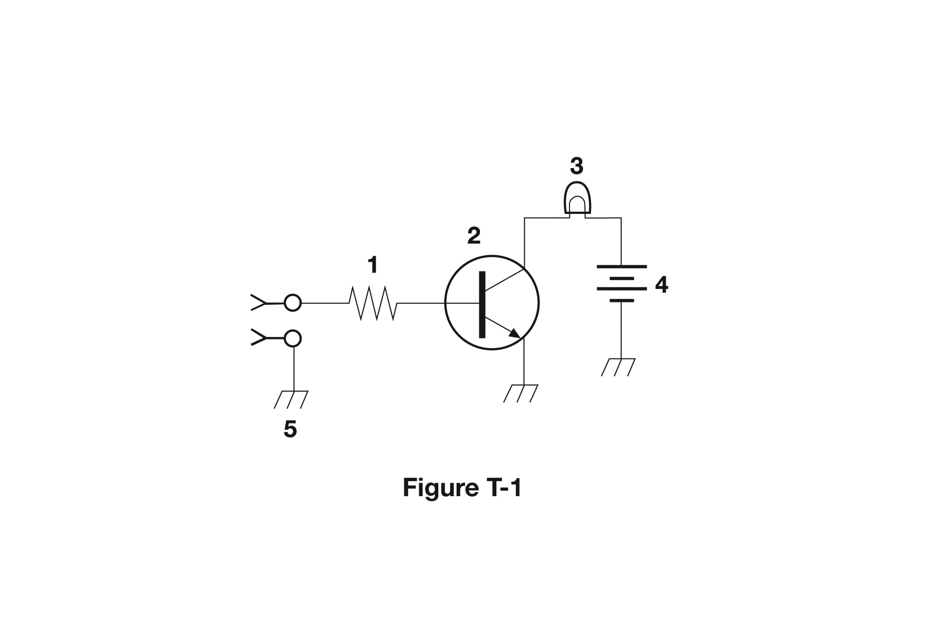
Why In figure T-1, component 1 is drawn as the classic zigzag (or in IEC style a plain rectangle) in line with the wire, which is the schematic symbol for a resistor. A resistor has just two leads and no polarity marking, so the symbol looks the same from either end. Component 1 is the only zigzag element in that figure, which is why it is identified as the resistor.
Watch out The transistor answer is the common trap, but a transistor symbol has three leads and a circle with an arrow on the emitter, which is component 2 in this same figure.
Zigzag = resistance to the flow. Two leads and no arrow means resistor.
HamSandwich explanation, first draft. The question and answers are the NCVEC text.
What is component 2 in figure T-1?
Why In Figure T-1, component 2 is drawn as a circle containing a vertical base bar with two leads coming off it, one of which carries an arrowhead. That arrow on the emitter lead is the giveaway for a bipolar transistor, and the direction it points tells you whether the device is NPN (arrow pointing out, Not Pointing iN) or PNP. The three terminals are base, emitter and collector, which is what lets the part amplify or switch.
Watch out A resistor is a simple zigzag (or plain rectangle) with just two leads and no circle or arrow, so it cannot be the three-terminal device shown here.
Circle + arrow + three leads = transistor. Arrow Not Pointing iN means NPN.
HamSandwich explanation, first draft. The question and answers are the NCVEC text.
What is component 3 in figure T-1?
Why In Figure T-1, component 3 is drawn as a circle with an X (crossed lines) inside it, which is the standard schematic symbol for an incandescent lamp or indicator bulb. The circle represents the glass envelope and the crossed lines stand for the filament supports. Figure T-1 also contains a resistor (zigzag or rectangle), a transistor (circle with three leads and an arrow), and a battery, so learning which number goes with which symbol is what this question tests.
Watch out The transistor is the nearby symbol with three leads and an arrowhead on the emitter, and a ground symbol is a set of stacked horizontal bars or a triangle at the end of a single lead, not an enclosed circle.
Circle with an X = lamp lit up. In T-1: 1 resistor, 2 transistor, 3 lamp, 4 battery.
HamSandwich explanation, first draft. The question and answers are the NCVEC text.
What is component 4 in figure T-1?
Why In Figure T-1, component 4 is drawn as a stack of alternating long and short parallel lines, the standard symbol for a battery or DC source. The long line is the positive terminal and the short, thicker line is the negative terminal; multiple pairs suggest several cells in series. It is the energy source feeding the rest of that circuit.
Watch out The ground symbol is the tempting confusion because it is also a set of stacked horizontal lines, but ground lines all get progressively shorter and are the same weight, with no long/short alternation and only one connecting lead.
Battery = long and short lines alternating (long = +). Ground = lines that just shrink to a point.
HamSandwich explanation, first draft. The question and answers are the NCVEC text.
What is component 6 in figure T-2?
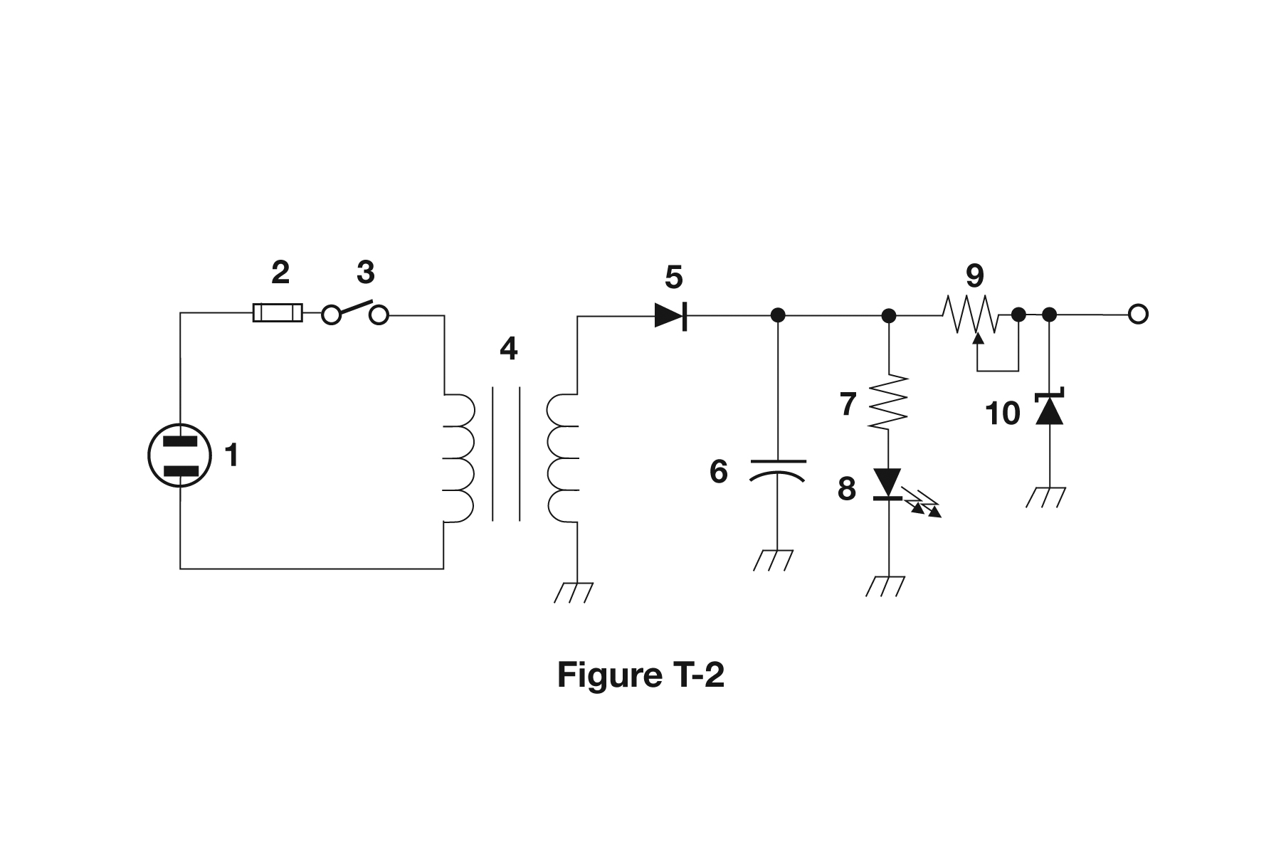
Why In Figure T-2 component 6 is drawn as two parallel lines facing each other with a gap between them, which is the standard schematic symbol for a capacitor. The symbol literally pictures the device: two conductive plates separated by an insulating dielectric that stores energy in an electric field. If one plate is drawn curved or the symbol has a plus sign, it is a polarized (electrolytic) capacitor, but it is still a capacitor. In this power supply diagram it sits across the output to filter, or smooth, the rectified DC.
Watch out A resistor is drawn as a zigzag (or a plain rectangle in IEC style) and a transistor shows three leads meeting a base bar inside a circle, so neither matches the two-plate symbol here.
Two parallel plates with a gap = capacitor; zigzag = resistor; coil = inductor.
HamSandwich explanation, first draft. The question and answers are the NCVEC text.
What is component 8 in figure T-2?
Why Component 8 carries the standard diode symbol, a triangle pointing into a bar, with two small arrows drawn pointing away from it. Those outward arrows mean the device emits light, so it is a light emitting diode. Current flows from the triangle (anode) toward the bar (cathode), and an LED almost always needs a series resistor to limit that current.
Watch out A regulator IC in these figures is drawn as a plain rectangle or box with three labeled leads (input, output, ground), not a triangle and bar; arrows pointing toward a diode instead of away would make it a photodiode or light-sensitive device.
Arrows pointing AWAY from the diode = light going out = LED. Arrows pointing in = light coming in.
HamSandwich explanation, first draft. The question and answers are the NCVEC text.
What is component 9 in figure T-2?
Why A diagonal arrow drawn through a component body is the schematic convention for 'variable' or adjustable. Component 9 has that arrow crossing the zigzag (or rectangular) resistor body, so it is an adjustable resistance such as a potentiometer or rheostat. Identify these symbols in two steps: first read the body shape to get the component type, then look for the arrow that makes it adjustable.
Watch out A variable inductor would show the arrow crossing a coil of loops, and a variable capacitor would show it crossing two parallel plates, neither of which appears at position 9.
Arrow = variable. Then read the body: zigzag is a resistor, coil is an inductor, two plates is a capacitor.
HamSandwich explanation, first draft. The question and answers are the NCVEC text.
What is component 4 in figure T-2?
Why In Figure T-2, component 4 is drawn as two coil windings facing each other with parallel lines between them representing an iron core. That is the standard schematic symbol for a transformer, which couples AC energy from a primary winding to a secondary winding by magnetic induction and changes voltage according to the turns ratio.
Watch out A variable inductor would be a single coil with an arrow drawn through or across it; the tell for a transformer is the second winding plus the core lines between the two coils.
Two coils face to face with core lines between = transformer. One coil alone = inductor.
HamSandwich explanation, first draft. The question and answers are the NCVEC text.
What is component 3 in figure T-3?
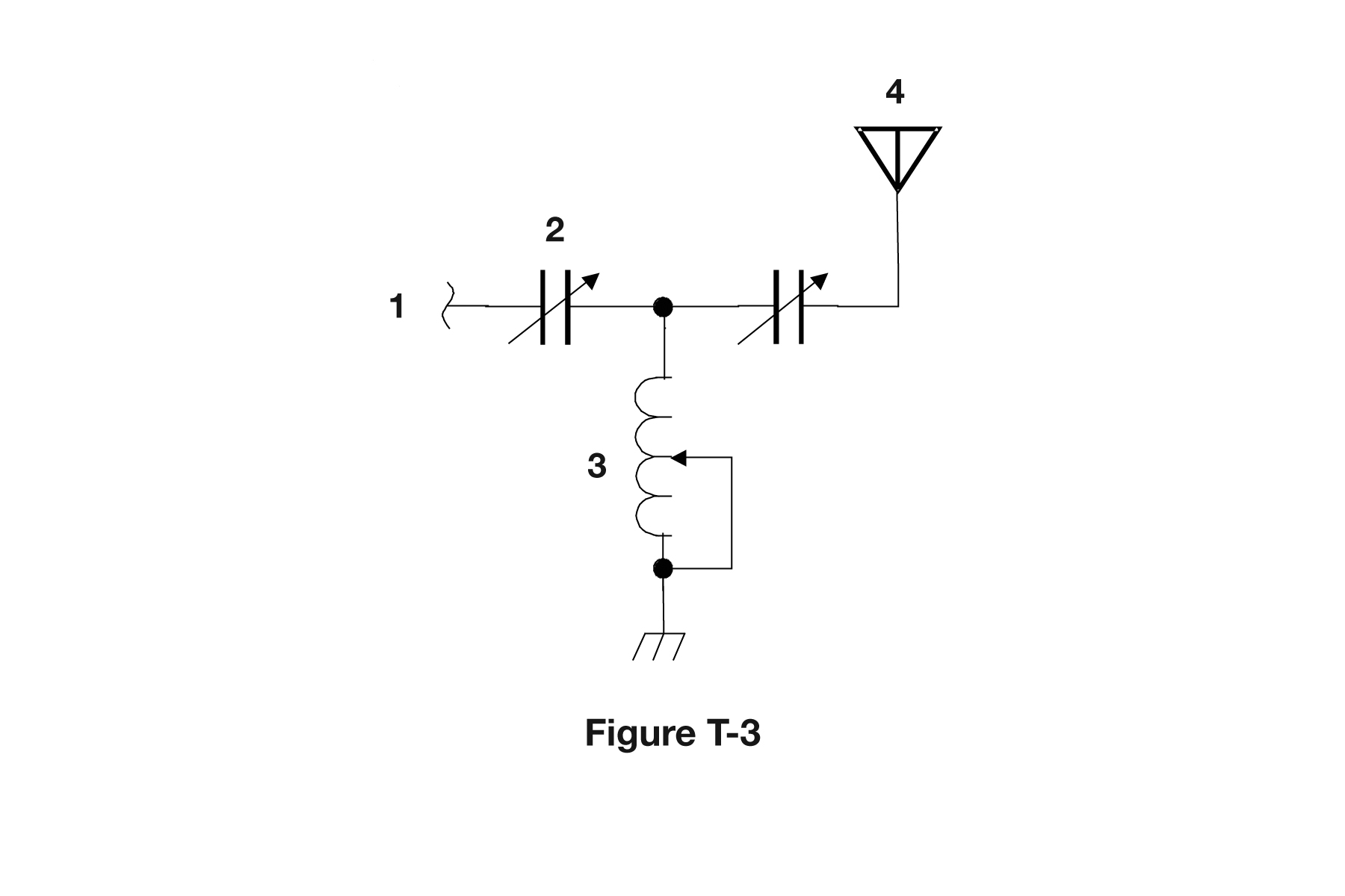
Why In figure T-3 component 3 is drawn as a coil, a series of loops or humps along the wire, which is the schematic symbol for an inductor, and it has an arrow drawn through it meaning the value is adjustable. An arrow across any component symbol is the standard way to show that it is variable or tunable. So a coil plus an arrow is a variable inductor, the kind of tuning coil found in antenna tuners and matching networks.
Watch out The variable capacitor choice is the closest trap: a capacitor is drawn as two short parallel lines or plates, not a coil, so an arrow through plates would be the variable capacitor instead.
Loops = inductor, plates = capacitor, arrow through it = variable. Coil + arrow = variable inductor.
HamSandwich explanation, first draft. The question and answers are the NCVEC text.
What is component 4 in figure T-3?
Why In Figure T-3 the item labeled 4 is drawn as a vertical line topped by two diagonal lines forming an open V, which is the standard schematic symbol for an antenna. It sits at the output end of the circuit, which is where a transmitted signal is radiated. Figure T-3 is a simple transmitter chain, so the last element after the filtering and amplifying stages is the radiating element.
Watch out The ground symbol is easy to confuse with it, but ground is drawn at the bottom of a circuit as a stack of shortening horizontal bars or a solid triangle pointing down, not an open V pointing up.
Open V pointing up and out equals antenna radiating; stacked bars pointing down into the earth equals ground.
HamSandwich explanation, first draft. The question and answers are the NCVEC text.
Which of the following is accurately represented in electrical schematics?
Why A schematic is an electrical map, not a physical one. It shows which component terminals connect to which, using standardized symbols, so you can trace signal and current paths. Physical details like where parts sit on the board, how long the wires are, or what the parts look like come from a pictorial or layout drawing instead.
Watch out Physical appearance is tempting because symbols sometimes loosely resemble the part (a coil for an inductor), but the symbol is a convention, not a picture of the actual component.
Schematic = what's connected, not where it sits or how long the wire is.
HamSandwich explanation, first draft. The question and answers are the NCVEC text.