T6C08
ELECTRONIC AND ELECTRICAL COMPONENTS · Circuit diagrams: use of schematics, basic structure; Schematic symbols of basic components
T6C08T6C →
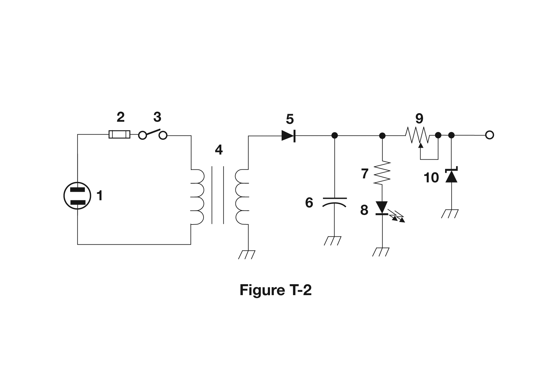
What is component 9 in figure T-2?
- AVariable capacitor
- BVariable inductor
- CVariable resistor
- DVariable transformer
Why A diagonal arrow drawn through a component body is the schematic convention for 'variable' or adjustable. Component 9 has that arrow crossing the zigzag (or rectangular) resistor body, so it is an adjustable resistance such as a potentiometer or rheostat. Identify these symbols in two steps: first read the body shape to get the component type, then look for the arrow that makes it adjustable.
Watch out A variable inductor would show the arrow crossing a coil of loops, and a variable capacitor would show it crossing two parallel plates, neither of which appears at position 9.
Arrow = variable. Then read the body: zigzag is a resistor, coil is an inductor, two plates is a capacitor.
HamSandwich explanation, first draft. The question and answers are the NCVEC text.
The rest of T6C
- T6C01 What is an electrical diagram using standard component symbols called?
- T6C02 What is component 1 in figure T-1?
- T6C03 What is component 2 in figure T-1?
- T6C04 What is component 3 in figure T-1?
- T6C05 What is component 4 in figure T-1?
- T6C06 What is component 6 in figure T-2?
- T6C07 What is component 8 in figure T-2?
- T6C08 What is component 9 in figure T-2?
- T6C09 What is component 4 in figure T-2?
- T6C10 What is component 3 in figure T-3?
- T6C11 What is component 4 in figure T-3?
- T6C12 Which of the following is accurately represented in electrical schematics?