T6C05
ELECTRONIC AND ELECTRICAL COMPONENTS · Circuit diagrams: use of schematics, basic structure; Schematic symbols of basic components
T6C05T6C →
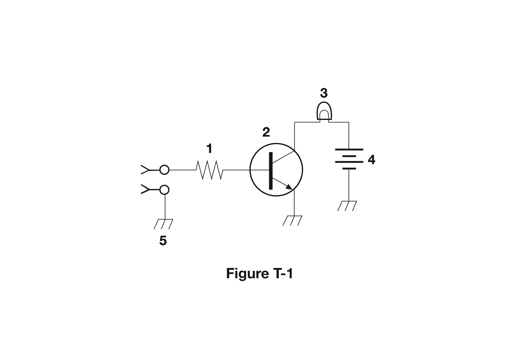
What is component 4 in figure T-1?
- AResistor
- BTransistor
- CGround symbol
- DBattery
Why In Figure T-1, component 4 is drawn as a stack of alternating long and short parallel lines, the standard symbol for a battery or DC source. The long line is the positive terminal and the short, thicker line is the negative terminal; multiple pairs suggest several cells in series. It is the energy source feeding the rest of that circuit.
Watch out The ground symbol is the tempting confusion because it is also a set of stacked horizontal lines, but ground lines all get progressively shorter and are the same weight, with no long/short alternation and only one connecting lead.
Battery = long and short lines alternating (long = +). Ground = lines that just shrink to a point.
HamSandwich explanation, first draft. The question and answers are the NCVEC text.
The rest of T6C
- T6C01 What is an electrical diagram using standard component symbols called?
- T6C02 What is component 1 in figure T-1?
- T6C03 What is component 2 in figure T-1?
- T6C04 What is component 3 in figure T-1?
- T6C05 What is component 4 in figure T-1?
- T6C06 What is component 6 in figure T-2?
- T6C07 What is component 8 in figure T-2?
- T6C08 What is component 9 in figure T-2?
- T6C09 What is component 4 in figure T-2?
- T6C10 What is component 3 in figure T-3?
- T6C11 What is component 4 in figure T-3?
- T6C12 Which of the following is accurately represented in electrical schematics?